|
Vehicles
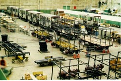 The 51 AIRTRANS personnel vehicles and 17 utility vehicles are on the same chassis and have the same basic controls. The passenger and employee vehicles are identical except they are inserted in the guideway with opposite ends in front to provide for the door on the right or left to correspond to the location of the employee or passenger stations which are on opposite sides of the guideway. (The employee stations are on the right and passenger stations on the left of the direction of travel). The vehicle is 21-ft. long, 7-ft. wide, and 10-ft. high. It has an empty weight of 14,000 lbs. In addition to the bi-parting entrance door, there is an emergency exit on each end of the vehicle. Exterior panels are of acrylic-coated fiberglass with the colors impregnated in the acrylic finish. Vehicles were produced in the high bay manufacturing area of LTV Aerospace Corp. in Grand Prairie, Texas. The final assembly line for production of A-7 aircraft may be seen in the background of the Vehicle Assembly illustration that shows production of the AIRTRANS vehicles. The 51 AIRTRANS personnel vehicles and 17 utility vehicles are on the same chassis and have the same basic controls. The passenger and employee vehicles are identical except they are inserted in the guideway with opposite ends in front to provide for the door on the right or left to correspond to the location of the employee or passenger stations which are on opposite sides of the guideway. (The employee stations are on the right and passenger stations on the left of the direction of travel). The vehicle is 21-ft. long, 7-ft. wide, and 10-ft. high. It has an empty weight of 14,000 lbs. In addition to the bi-parting entrance door, there is an emergency exit on each end of the vehicle. Exterior panels are of acrylic-coated fiberglass with the colors impregnated in the acrylic finish. Vehicles were produced in the high bay manufacturing area of LTV Aerospace Corp. in Grand Prairie, Texas. The final assembly line for production of A-7 aircraft may be seen in the background of the Vehicle Assembly illustration that shows production of the AIRTRANS vehicles.
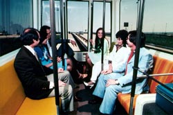 The vehicle interior, provides seating space for 16 people and standing room for an additional 24, for a total of 40 passengers. Hand holds and colors were carefully selected to blend with the color scheme of the airport. The floor is carpeted and the seats are upholstered. The vehicle contains a public address system , two-way voice communication equipment, and an on-board automatic station announcement system. Vehicle controls are located under the carry on luggage rack. The vehicle chassis is made as a welded structural steel frame. Axles are a standard automotive truck type, with one driven through a standard differential. They are supported by an air bag suspension system and foam-filled tires, size 8.25x20. The innovative use of existing and proven hardware in a new concept transit system resulted in lower cost, greater reliability, and a long service life. Propulsion is by a continuous rating d/c motor driving through the automotive drive shaft to the differential. The 480 V a/c. source power is rectified and controlled by a motor controller located on the chassis under the floor of the vehicle. Also under the floor is the emergency storage battery, an alternator to charge the battery, an air compressor for the suspension system, door operator, brakes, and vehicle dock leveling system. Two heating and air-conditioning units are suspended below the chassis one on each side. A nominal 5 tons of air-conditioning is provided. The vehicle interior, provides seating space for 16 people and standing room for an additional 24, for a total of 40 passengers. Hand holds and colors were carefully selected to blend with the color scheme of the airport. The floor is carpeted and the seats are upholstered. The vehicle contains a public address system , two-way voice communication equipment, and an on-board automatic station announcement system. Vehicle controls are located under the carry on luggage rack. The vehicle chassis is made as a welded structural steel frame. Axles are a standard automotive truck type, with one driven through a standard differential. They are supported by an air bag suspension system and foam-filled tires, size 8.25x20. The innovative use of existing and proven hardware in a new concept transit system resulted in lower cost, greater reliability, and a long service life. Propulsion is by a continuous rating d/c motor driving through the automotive drive shaft to the differential. The 480 V a/c. source power is rectified and controlled by a motor controller located on the chassis under the floor of the vehicle. Also under the floor is the emergency storage battery, an alternator to charge the battery, an air compressor for the suspension system, door operator, brakes, and vehicle dock leveling system. Two heating and air-conditioning units are suspended below the chassis one on each side. A nominal 5 tons of air-conditioning is provided.
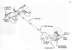 The vehicle steering system is another system patent of LTV Aerospace. Steering is accomplished with 6-inch diameter polyurethane wheels, which are fixed to a guide bar that is connected to the steering linkage. The front wheels are linked to the rear wheels, so that tread-over-tread tracking takes place. As the front wheels steer in one direction the rear wheels steer in the opposite direction. The steering mechanism is directional; therefore a reversing mechanism is provided to reverse the sense of the steering for vehicle operation in the opposite direction. The vehicle steering system is another system patent of LTV Aerospace. Steering is accomplished with 6-inch diameter polyurethane wheels, which are fixed to a guide bar that is connected to the steering linkage. The front wheels are linked to the rear wheels, so that tread-over-tread tracking takes place. As the front wheels steer in one direction the rear wheels steer in the opposite direction. The steering mechanism is directional; therefore a reversing mechanism is provided to reverse the sense of the steering for vehicle operation in the opposite direction.
 The switching wheels are located in a fixed position above the steering wheels. These wheels steer against the outside of or become entrapped under the switch rail, thus steering the vehicle through the switch. In a switch area, one wheel is always entrapped under a rail, providing protection against splitting a switch. Additional safety is provided by backup smaller diameter steering and switching wheels just ahead of the service wheels. These come into play only in case of failure of the service wheels. The switching wheels are located in a fixed position above the steering wheels. These wheels steer against the outside of or become entrapped under the switch rail, thus steering the vehicle through the switch. In a switch area, one wheel is always entrapped under a rail, providing protection against splitting a switch. Additional safety is provided by backup smaller diameter steering and switching wheels just ahead of the service wheels. These come into play only in case of failure of the service wheels.
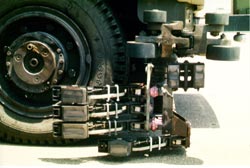
Power collection is by three articulated brushes, a set on each corner of the vehicle, with two sets in normal use for redundancy. The vehicle wheel illustration shows these, as well as the upper brush, which collects the wayside signal and the lower brush, which provides vehicle earth grounding. A vehicle bumper permits non-damaging impacts at speeds up to at least 3 mph. A draw bar and umbilical allows two-car trains to be operated.
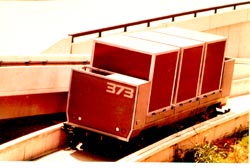 The 17 utility vehicles have a chassis identical to that of the passenger vehicle. The car body is replaced with a powered flattop conveyor bed and framework. The conveyor drive has controls, which automatically power containers on or off the vehicle onto similar powered conveyors at the baggage, mail, trash, and supply stations. These controls are located in a compartment at the end of the vehicle. The vehicle can also carry and automatically handle the airlines standard LD3 container. (As of 1998 the utility vehicles no longer existed as all have been converted to passenger vehicles to satisfy increased passenger loads; and trash, supplies, mail, and baggage are being handled in other ways.). The 17 utility vehicles have a chassis identical to that of the passenger vehicle. The car body is replaced with a powered flattop conveyor bed and framework. The conveyor drive has controls, which automatically power containers on or off the vehicle onto similar powered conveyors at the baggage, mail, trash, and supply stations. These controls are located in a compartment at the end of the vehicle. The vehicle can also carry and automatically handle the airlines standard LD3 container. (As of 1998 the utility vehicles no longer existed as all have been converted to passenger vehicles to satisfy increased passenger loads; and trash, supplies, mail, and baggage are being handled in other ways.).
Airtrans:
Program Background
System Requirements and LTVs Proposed Solution
Guideway
Switch and Switch Machine
Power Distribution
Vehicles
Controls
Stations
Maintenance
Airtrans Today
|