|
|||||||

|
Voughts design used the conventional, straight low-wing configuration with NACA 65-212 airfoil. Not only did airfoils of this series have lower form drag (CDo) due to laminar flow over the forward portion of the airfoil, but the series (also known as supercritical) had a higher drag-rise Mach number than the older NACA airfoils, such as the symmetrical 0012 or cambered 23012 of equal thickness. In addition, the XF6U-1 had the new NACA-developed leading edge air inlet in the left and right wing roots.
Armament consisted of four 20-mm cannons in the fuselage nose section. Gun gas ports were near the engine air inlets. Early gun-pit firing tests caused come concern about ingestion of gun gas into the air inlets. Gun tests did not progress far enough to show flight effects. The airplane had large outboard trailing-edge plain flaps for roll control. These ailerons used the new NACA internal overhang balance with curtain seal and 40% proportional power boost to reduce lateral stick forces to under 10 pounds. Inboard slotted extensible flaps were used for high lift. The wing had enough dihedral to make roll due to yaw (Cl) = 0.002. The vertical tail was sized to make (Cn) = -0.002. These were specification values at the time. The horizontal stabilizer and elevator were sized for a 3% MGC (mean geometric wing chord) minimum stick-fixed static margin and a c.g. range of 12% MGC. A bobweight was sized for proper stick force per g. The elevators had trim tabs and linked balance tabs for stick force tailoring. Low-speed wind tunnel tests conducted at MIT confirmed the predicted flying qualities. High-speed wind tunnel tests were not considered essential, which was shortsighted considering flight test compressibility problems, the need for swept wings, and the addition of an afterburner to attain transonic performance.
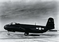
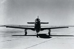
The XF6U-1 had tricycle landing gear (a Vought first), a bulbous canopy for side and down vision, wing-root air inlets, four cannon ports, and unique bulbous wing tips. The latter were to allow wing-tip tanks to roll away, without ejection, when released. More F6U: Design
|
 The most outstanding design feature of the XF6U-1 was the Metalite panels used to cover the wing, fuselage and tails. Metalite had first been used successfully on Voughts XF5U-1 airplane. Metalite panels of low-density balsa wood core, bonded on both sides to aluminum skin, were formed in molds, cured in a large autoclave and joined at wing ribs or fuselage bulkheads with flush rivets. The inherent stiffness of the Metalite panels minimized the number of ribs or stiffeners required for a strong, low-weight structure. Close tolerances on mating panels and Navy glossy paint made the finished airplane an aerodynamicists dream of mirror smoothness and low drag.
 The XF6U-1 had unsymmetrical jet-engine exhaust. The question of induced power effects was answered in the 7x10-foot low-speed wind tunnel of United Aircraft Research Division, in Hartford Connecticut. To simulate engine exhaust, six commercial portable air compressors were rented and their combined output piped into the 0.15-size wind tunnel model. By operating the compressors at full flowrates, it was shown that pitching moment induced by thrust was zero at several wind tunnel airspeeds.