|
|||||||

|
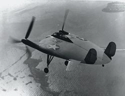
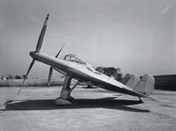
What made airplanes fly was the stuff that young NACA engineers lived and breathed. This fascination led Zimmerman to design the V-173 as a flying wing, to minimize wetted area and parasite drag, and to put the propellers at the wing tips, rotating so as to oppose induced drag. It was known that a finite aspect ratio wing had a bound lifting vortex along the quarter chord line which, when viewed from the rear, rotates clockwise at the port (left) wing tip, and counterclockwise at the starboard (right) wing tip, causing downwash aft and rotates the lift vector back to cause induced drag such that: CDi = CL2/pe Aspect Ratio Where e is the airplane efficiency factor determined by wind tunnel test.
CDi = CL2/pe (1-FOO) Aspect Ratio Thats right, it was called FOO Factor or FQ , and had theoretical values from 0 to 1 or more, depending on shaft horsepower. With power off, FOO=0 and induced drag was proportional to lift coefficient squared and inversely proportional to wing aspect ratio. In a high-powered climb, FOO could be greater than one and induced drag became induced thrust. This was true not only theoretically, but actually, as shown by powered tests of a 1/3-scale V-173 model in the Langley full-scale wind tunnel (December 1941). Numerous free-flight (rubber-band and electricpowered) and captive wind tunnel tests were conducted between 1933 and 1943. These tests showed that:
Twin fins and rudders were always part of the design for directional stability and control. More V-173: Advanced Design Concepts
|
 To best appreciate the very-advanced V-173 design concept, one must go back to 1930 when Charles Zimmerman graduated from the University of Kansas with a degree in electrical engineering and an introductory course in aerodynamics that helped him secure a job with NACA. Initially, Zimmerman made a name for himself by designing a free-spinning wind tunnel and then a free-flight wind tunnel.
 Zimmerman knew that a right-hand propeller generates a strong right rotational component to the slipstream. Hence, a right-hand propeller on the starboard wing tip and a left-hand propeller on the port wing tip should reduce induced drag. The theory of wing lift and induced drag, together with experimental data available for propeller slipstream rotation lead to: