|
The Next Step - Afterburning
The transition from reciprocating to turbo-jet power plants on high performance aircraft was rapid and complete. The change was somewhat unusual compared to similar events in engineering history in that, although the new power plant is utterly unlike the old, the new type has undergone no basic changes in the five years since its conception. All the turbo-jet engines in use today are fundamentally similar to the original Whittle engine; they use the same thermal cycle and have only one controlled variable, the RPM. Component efficiencies and structural design have, of course, improved and the specific performance of modern turbo-jet engines is far above that of the original engines.
Various other power plant types have been discussed In the literature, the turbo-propeller, the ducted fan and numerous variations of these and the turbo-Jet engine involving interceding, regeneration, reheat, and afterburning. Of these, the addition of afterburning to a simple turbo-jet engine appears the nearest to a practical solution.
The use of afterburning offers attractive performance advantages, and requires such a minimum of additional complexity that it seems probable that it will mark the next major step in the progress of aircraft power plants.
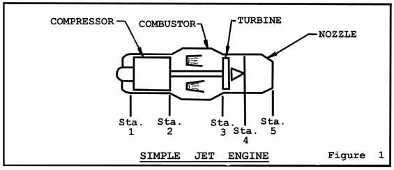
Figure 1 shows the schematic arrangement of the basic components of a simple turbo-Jet engine. The power output of such an engine is limited by the amount of fuel, which can be added without exceeding the temperature limits of the turbine blades. To maintain the required temperature after combustion it is necessary to operate at very lean fuel-air ratios, and the exhaust gas from the combustion chamber contains a large amount of excess oxygen. Since it is not possible to add any additional heat in the combustion chamber, and since heat must be added to the working fluid under pressure, if useful work is to be obtained, the other station at which heat may be added is Station 4, downstream of the turbine and upstream of the exhaust nozzle. Since there is unburned oxygen in the gases discharging from the turbine, heat may be added by introducing fuel into a suitable combustion chamber. This is known as afterburning, and a schematic diagram of the system is shown on Figure 2.
|